Engineering, Procurement & Construction Best Practice Guidelines (Version 2.0)
Do you prefer the guidelines as a pdf file?
Download PDFAre you interested in downloading a specific chapter?
Search the reports?
SearchEngineering
The engineering design and modelling of a PV plant is a crucial element of the EPC lifecycle, as it guides the whole process of EPC, from conceptualisation to investment decisions and to the actual construction of the solar power plant. It is also a highly iterative process in which inputs from all the main stakeholders are considered, to generate the most suitable project plan for a successful and efficient PV plant.
As a best practice, all locally applicable standards and permitting procedures shall be clearly described and considered at the very start of the design process. Later, different stakeholders may have different engineering and design requirements to perform their respective services. Good communication and timely adjustments of the engineering design along the way are strongly recommended to ensure quality throughout the entire process.
In the following chapter, the engineering stage of the project has been divided into four sub-phases, which are considered the common flow for PV project development. However, some of these phases (and milestones) may differ from the reader’s project due to different companies’ business approaches or philosophies, types of project finance, number of stakeholders and project size.
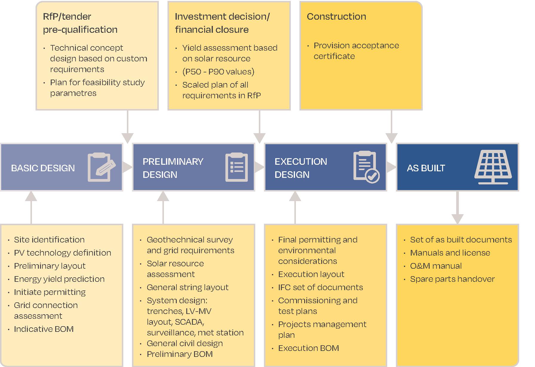
Starting off as a basic technical concept, the engineering design is itself a process that evolves and is constantly refined as the project development advances. It evolves into a detailed execution design blueprint issued for construction. Once construction and commissioning are completed, a detailed set of “as built” documents is handed over to the O&M service provider.
6.1. Basic design
The basic design concept is the first assessment of the engineering design, and it is sometimes considered to be a part of the early “project development” (see Chapter 2 on Definitions in SolarPower Europe’s Lifecycle Quality Guidelines). At this stage, the developer may not have a clear understanding of the project site characteristics such as topography, hydrology, and obstacles. The main objective of the design concept at this early stage is to verify the project feasibility.
Generally, the basic design concept includes an initial layout (preliminary layout in Fig.3) for the plant, energy yield simulation, grid connection assessment and an indicative bill of materials (BOM in Fig.3) for the main components only:
- PV modules – manufacturer, model, and power class(es)
- Inverters - manufacturer and model
- Tracking system (if present) - manufacturer and model.
Using simulation software to compare different sets of module or inverter technologies, as well as mounting structures and different plant layouts can be beneficial in choosing the optimal design in terms of predicted energy yield and cost structure.
Usually, the basic design concept with total installed capacity, indicative layout design and single line diagram (SLD) is sufficient to start the permitting process.
However, more detailed versions of the basic design concept may be produced to facilitate early development permitting milestones or bidding in tender procedures, depending on the concrete case requirements.
Establishing design requirements and conducting requirement analysis are the most important elements in the design process, and this task is often performed at the same time as a feasibility analysis.
On top of basic things like the functions, attributes, and specifications, determined after assessing user needs, some design requirements may also include hardware and software parameters, maintainability, availability, and testability.
Maintainability requirements:
- The support structure should allow grass cutting, panel cleaning, and preserve a sustainable ecosystem
- There should be enough space between PV rows, and between rows and fences
- On roofs, there should be maintenance walkways
- The fixation of string cables should keep the connectors far from rain
- The drainage system should be designed to remove water in an efficient way without high OPEX and to avoid flooding
- The security system should be designed to allow for efficient protection of the plant at moderate OPEX
- The monitoring system should allow for quick error detection and efficient fault analysis (see SolarPower Europe’s O&M Best Practice Guidelines for requirements)
- It should be possible to have affordable service contracts for core elements like inverters and switch gear
As the project advances, the developer will acquire more information, provided that the following studies are performed: site assessment, solar resource analysis, environmental studies, permitting requirements and interconnection assessment.
The design can be updated respectively with:
- Preliminary Layout with Installed Capacity: Wp and Wac
- Layout constraints and boundaries
- Indicative bill of materials of major equipment: modules, inverters, type of structure, transformers
- Preliminary SLD
- Yield simulations with proposed losses assumptions for availability, soiling, cabling losses
Then, project documentation is ready for the technical due diligence usually required by investors, especially, if the power plant is financed through project finance.
An indicative list of documents is provided at the Annex F, section Basic Design, as a guideline for the developers on how to initiate a project, seek permitting and advance to the technical due diligence stage.
It is a best practice that the design development is done in close coordination with the stakeholders involved such as investors, local communities, banks, suppliers, grid operators, national and local authorities, etc. The more detailed and stakeholder-agreed the design is, the better it will support the development of the project’s financial model.
As a best practice, the technical viability of the design needs to be confirmed. The proposed suppliers of the main components need to be checked for a satisfactory track-record and relevant warranties. These steps are especially important when utility scale and commercial & industrial (C&I) projects are considered. Those financial stakeholders who do not have their own internal technical teams may instead rely on specialised technical advisors to conduct the relevant studies and reports and confirm the quality of the basic design.
6.2. Preliminary design
A detailed basic design usually provides sufficient basis for taking an investment decision or arranging finance. However, depending on the stakeholders involved, clearing that milestone may require more precise site topography measurements as well as regulatory and financial closure aspects to be accounted for in a preliminary design concept.
A key element of preliminary designs is a topographical survey. A ground-based site survey should be enhanced through a full topographical survey using a drone, which can produce site orthomosaics, Digital Elevation Models (DEM), and Point Cloud maps. Using a drone to collect the terrain and shading scene (both near and horizon) is vital in ensuring an optimal array design for a given area of land. If an EPC service provider is contemplating using bi-facial modules, then an albedo estimate can also be made from the drone photogrammetry.
Computer Aided Design (CAD) based software will ingest these 3D models to produce the topographical layouts of the PV plants where all elements are in their true geographical locations, to an extremely high level of accuracy and precision.
In any situation, the present section, and the Annex F, section Preliminary Design are an indicative guideline for the phase’s steps and documentation.
The preliminary design shall be part of the Pre-Construction Documentation, where the layout shall propose:
- PV Array sections
- Inverter Stations
- Mounting systems or trackers
- Substation
- Communication systems
- Monitoring systems1
- Cable routes
- Access roads
- Laydown areas
- Meteorological stations
- Site tracks
- Manholes
- Construction area
- Permanent and temporary buildings
The preliminary design shall include a preliminary bill of materials (preliminary BOM in Fig. 3) for budgeting purposes. The bill of materials gives quite a precise indication of quantities, so that (binding or non-binding) term sheets can be collected from suppliers and contractors.
The topographical survey and layouts of PV plants can be used as a 3D model to generate a preliminary digital twin of a PV plant, intended as a tool to visualise the asset. The information related to the choice and selection of components are part of the PV Information Modelling can also be visualised within the digital twin.
In projects where a turnkey EPC contract is signed, the design is only approved by the Asset Owner or the developer, and the EPC service provider is responsible for providing all the contracts and suppliers.
If an EPC service provider has already been involved in the design phase, the set of documentation shall include the projects’ buildings, amenities, preliminary studies, quality and testing plans, as well as the method statement, in addition to the layout and equipment specification.
At this stage, the Owner/Developer shall also agree with the EPC service provider on the Project Management Plan, including the project reporting, EHS, quality, changing plans and document register.
A detailed overview of the documentation of this stage can be found at Annex F, section Preliminary Design.
[1] For the selection of the Monitoring System, see Chapter 9 of the O&M Best Practice Guidelines on Data and monitoring requirements, as well as the best practice checklist for monitoring tools, available at www.solarbestpractices.com.
6.3. Executive design
As the preliminary design is changed and/or approved by the Owner, the EPC service provider shall move to the execution design stage, incorporating all the relevant construction blueprints and working instructions.
Once the design is finalised, it shall provide all the information necessary to request a grid connection, as well as all the necessary parameters for a grid impact analysis (if required).
A fully detailed specification of equipment and bill of materials (including the spare parts) shall be produced. As part of the execution design, the construction plans would have the final reports of calculations and assessments for all electrical and civil structures.
Factory acceptance plans shall be defined for major equipment. In addition, commissioning and testing procedures shall be provided to the Owner/developer for verification and approval.
It is recommended that a list of companies, major machinery, number of personal involved in the construction phase and quality assurance measures planned be included in project management plans. A method statement shall be clearly defined for each project phase.
A detailed overview of the documentation of the execution stage shall be found at Annex F, section Execution Design.
For large assets drone-based construction monitoring is recommended during construction. This data provides an excellent risk management tool and helps ensure the integrity of construction vs design plans by capturing any deviations or design changes as they occur.
6.4. As-built design
After the PV plant is accepted by the Asset Owner or the developer via the Provisional Acceptance Certificate (PAC) (see also section 9.3. Provisional Acceptance Certificate), the project enters the handover stage. This is the phase of the project where the EPC service provider shall deliver all the design documentation that details how the PV plant has been built (as-built design documentation). This is important to emphasise, because during the construction phase some of the execution design may change due to unexpected events, mistakes on the design, terrain, or underground difficulties.
A dimensionally and geospatially accurate ‘as-built’ model of the asset can be generated from the drone-captured construction monitoring data, which can be used to update the digital twin. If construction monitoring has not been undertaken, then a single photogrammetry flight can produce an as-built record of the visible array layout. It is also possible to generate a 3D model of the new asset for onward yield modelling and verification by using more enhanced photogrammetry approaches. Such data capture and modelling can be valuable as part of the handover documentation from the EPC service provider to the Asset Owner and the O&M service provider.
A detailed overview of the as-built documentation can be found in Annex F, section As-built Design (consider also IEC standard 62446).
In addition to the as-built design, the EPC service provider should also organise other handover documentation, such as the O&M manuals, for the Asset Owner and the O&M service provider. For more information, see Chapter 10 on Handover to O&M.