Engineering, Procurement & Construction Best Practice Guidelines (Version 2.0)
Do you prefer the guidelines as a pdf file?
Download PDFAre you interested in downloading a specific chapter?
Search the reports?
SearchEPC for PV power plants with storage
Energy storage technologies are instrumental in enabling the transition to a climate-neutral and renewable energy-based economy. As more renewable energy capacity is connected to the grid, the need for grid flexibility solutions is increasing. Energy storage technologies offer a solution that is commercially proven to increase the penetration rate of fluctuating renewable energy in the electricity system. One of its uses is storing surplus power when demand is low and shifting its use for times when demand is higher. In addition, energy storage systems (ESS) provide a wide range of ancillary services to the grid (e.g., balancing power, frequency, and voltage control, "black start", etc.), thus ensuring a stable, secure, and efficient operation of the energy system.
In this chapter, we will focus on ESS that are part of hybrid facilities (where generation and storage are either integrated or co-located) and how these systems can be used to better integrate solar power generation in the electricity system.
13.1. Types of storage systems
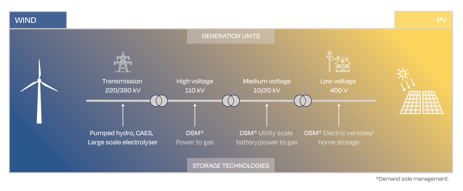
There are many forms of ESS: pumped hydro, compressed air, hydrogen, thermal, flywheels, supercapacitors, etc.
Green hydrogen, i.e., hydrogen produced from renewable sources, offers strong potential: it can be used for long-term (seasonal) storage, can be used in centralised or decentralised configurations (providing flexibility), solves intermittency issues, all by using existing gas storage technologies.
Another important, economically viable solution for utility scale solar plants in Europe are electrochemical storage systems. In the rest of the chapter, we will concentrate on the EPC aspects of these. The success of electrochemical storage systems in utility scale PV plants can be explained by the high compatibility of the size of typical storage solutions, and the voltage levels of both systems. Within this segment, Lithium-ion based solutions currently hold the biggest market share. During the last three years the deployment of redox-flow batteries (e.g., vanadium-based solutions) have increased. Lead-acid batteries, on the other hand, are still often the most economic choice for off-grid and smaller capacity systems in the residential sector and C&I solar plus storage systems.
At present, lithium-ion chemistries are the dominant storage technology for short-duration applications (i.e., 1 – 4 hours), representing ~90 % of the market (Lazard’s Levelized Cost of Storage Analysis (LCOS 6.0)). While lithium-ion chemistries currently dominate the utility-scale market, redox-flow batteries, based on their unique capability to decouple power and energy, are also gaining traction, particularly in use cases with long discharge times (several hours) and long storage durations (several days). In applications where high reaction speeds and partial power capabilities are a must (ancillary services) lithium-ion solutions have currently better overall efficiency values. In this case, partial power processing is technique that allows greater control over the battery charging current, improving the efficiency of the system whilst reducing power losses.
The type of a storage system can significantly influence a project’s overall design. Technical parameters such as battery lifetime, efficiency, charge/discharge rates and/or power density, should be taken into consideration at the development stage when selecting the most appropriate ESS design, coupling topology (AC vs. DC connection) and technology. The annual degradation rate of the battery should also be considered to determine if and when augmentation (battery replacement) will be needed. For this a clear use profile of the battery should be assumed.
Typically, the useful life of lead-acid batteries is estimated at between 1,000 and 1,500 cycles while lithium-ion batteries last between 2,000 and 6,000 cycles, and redox flow batteries can reach 15,000-20,000 cycles. The exact lifetime of the ESS is difficult to predict because it depends on the cumulative effect of multiple factors such as the number of cycles per year or day, average state of charge (SOC), depth of discharge (DoD), temperature and current ratings. Depending on the battery availability required, there are different recommendations for the percent of remaining capacity that triggers a replacement, generally ranging from 60 to 80 % of the initial capacity.
When evaluating Li-ion options for a solar plus storage project, battery chemistry should also be considered. In 2021, the two leading choices are lithium nickel manganese cobalt (NMC) and lithium ferro (iron) phosphate (LFP).
NMC has a higher energy density, which makes them better suited for electric vehicles and ESS that require frequent cycling for a relatively short period of time. On the other hand, the higher energy density carries higher risk for overheating and fire risk.
LFP, in contrast, is perceived as a safer option because it has high thermal stability. However, since LFP cells have lower energy density than NMC cells, they typically require more space to store the same amount of energy. Furthermore, the long-term performance of stationary storage systems based on LFP cells still needs to be proven.
13.2. Environment, Health & Safety
Most batteries are subject to environmental regulations that require recycling or proper disposal at the end of performance period. The most relevant one for Europe will be the upcoming regulation on batteries and waste batteries. This is still subject to negotiations between Member States and the European Parliament.
The ESS mentioned above are electrical appliances and carry significant H&S risks (DNVGL 2015). To prevent hazards (e.g., uncontrolled release of energy), an appropriate risk assessment must be performed during the design and planning phases, and necessary safety precautions implemented. The hazards must be identified during these stages and appropriate measures taken to mitigate risk and to protect those operating the system.
Both external and internal factors should be considered during the risk assessment since, in some cases, the ESS itself can be the cause of hazardous event. The major hazards for large-scale ESS can be categorized as follows:
- Electrical, occurring when there is direct contact between a person and the system (battery systems are typically designed to follow the low-voltage directive with a voltage range of 75-1500 V DC and 50-1000 V AC
- Mechanical, occurring after a physical collision
- Chemical - poisoning or exposure to hazardous materials through leaking of chemical components from the system, for example. This could be the non-aqueous electrolyte mix of a lithium-ion battery or the sulfuric acid in lead-acid or redox-flow batteries
- Other, occurring due to an explosion, fire, thermal runaway
To avoid risks, the system should not overheat or freeze, come into contact with water, or suffer from either electrical stress or high humidity. The risk of electrical shock can be mitigated - as is common practice in photovoltaic plants - with appropriate electrical insulation: for instance, by wearing appropriate personal protective equipment (PPE). The energy storage system should be maintained by trained technicians since improper handing increases the risk of electrical shock. For personnel qualifications during the installation and maintenance of stationary batteries, refer to IEEE 1657 - 2018.
Safety data sheets should be provided to those operating the system. In case of repair or replacement, addition or alteration of the system, the safety protocol should be re-evaluated and, if necessary, additional measures implemented.
It is good practice to design the system in a way that allows straightforward removal and replacement of modules, and separation between battery components and other equipment such as the Heating Ventilation, Air Conditioning (HVAC) or power conversion system (PCS) including inverter and transformer. The system itself should be easily accessible for inspection without needing to significantly disassemble the ESS system. Disposal of hazardous material should comply with local and national rules and regulations.
13.3. Engineering
Stationary energy storage can be separated into two categories based on the point of grid interconnection: Front-of-the-Meter (FTM); and Behind-the-Meter (BTM). The FTM applications focus on the operation of the electricity grid where energy storage systems are employed to maintain a smooth and continuous flow of electricity to the consumers. BTM applications are generally used to increase the self-consumption of a renewable unit behind the grid connection point of a consumer. When referring to utility-scale solar plus storage installations, BTM applications primarily use the ESS for energy shifting and/or self-balancing (See table).
| CATEGORY | APPLICATION/USE CASE | DEFINITION |
| FTM | Ancillary services | Provision or absorption of power to balance supply and demand and thus maintain the frequency of the grid at a reference value or reduce grid constraints: - Frequency regulation - Replacement for reserve spinning, non-spinning, and supplemental thermal generators - Voltage support - Reactive power compensation - Black start (recovery from a total or partial shutdown of grid) |
| FTM/BTM | Energy shifting (arbitrage) | EES is charged when market selling prices are low or energy would be clipped for other reasons (high DC/AC ratio at the inverter, maximum power limit for injection into grid, etc.). It is discharged to meet demand, sell at higher prices and/or smooth the production curve. Renewable energy assets coupled with storage essentially become dispatchable generation assets. |
| FTM/BTM | Self-balancing portfolio optimisation (Virtual Power plant) | Balance responsible parties (BRPs) and distribution system operators could use energy storage to reduce imbalance within portfolios to avoid imbalance charges. The BRP does not actively bid on the imbalance market using its load flexibility but uses it within its own portfolio. The combination of several assets at different grid connection points is known as virtual power plant (VPP). |
| BTM | C&I / Residential energy storage | Energy storage that is used to increase the rate of self-consumption of a PV system from C&I or residential customers or to reduce power consumption at the grid connection point to reduce grid connection costs. |
TABLE 5 - OVERVIEW OF FRONT-OF-THE-METER (FTM) AND BEHIND-THE-METER (BTM) APPLICATIONS AND DEFINITIONS
The first thing to consider at the start of the design and engineering process of a solar plus storage system is its application/use case and the related duty cycle specification, including a typical daily duty cycle over the lifetime of the system. The duty cycle analysis helps determine the minimum requirements for the energy capacity, power capability, and number of daily cycles, which are used as a starting point for the dimensioning. This phase is typically iterative as different commercially available solutions are evaluated in terms of their performance, lifetime, and cost. Software-assisted simulations are often used in this performance assessment in combination with yield assessments for the PV-plant. This step is important as it defines the required capacity of the system at the start of operation and influences the assumed oversizing and thus the capital expenditures of the project.
Another important aspect of the solar plus storage system engineering is deciding on the approach to be used for the ESS coupling (AC or DC) to the PV power plant. In AC-coupled systems, the solar and storage systems are connected to separate inverters. They can be dispatched together or independently.

In DC-coupled systems, solar and storage systems are connected on the same DC busbar and use the same inverter. They can only be dispatched together, as a single facility. DC-coupled systems further subdivide into loosely or tightly coupled – loosely coupled systems use a bidirectional inverter, so that the battery can charge from either the grid or the PV plant, while tightly coupled systems use a unidirectional inverter, meaning the battery can only charge from the PV plant.

Depending on the application, each approach has its advantages and disadvantages. The most common of these are listed in table, though each project will also have its own specific considerations, including the applicable regulatory framework and procurement choices.
| AC-COUPLED ESS | DC-COUPLED ESS |
| Advantages: - Higher operational flexibility - AC-coupled systems have the same efficiency when charging the battery from PV or the grid, and discharging is independent of the PV inverter - Faster reaction speed for ancillary service provision of battery system possible - To date, utility-scale systems have relied primarily on AC-coupled structures so more references are available - Easier to install when retrofitting existing PV plants | Advantages; - Higher round trip efficiency when charging from solar - Eliminates the need for one set of inverters, MV switchgear, and other balance of plant costs - Better suited to take advantage of oversizing PV (higher DC/AC ratio) and store otherwise clipped energy |
| Disadvantages: - Lower round-trip efficiency (more conversions are needed - PV inverter DC-AC, battery inverter AC-DC when charging, DC-AC when discharging) - Cannot take advantage of clipped energy, so it does not make sense to oversize the PV part much | Disadvantages: - Lower operational flexibility - the combined output of the PV and battery is limited by the size of the inverter, and if the inverter has a failure, both the energy storage and the PV generation is lost - More complex design & installation process (with DC coupling, the PV and batteries are paired on each inverter) - Certification of some components does not exist yet |
TABLE 6 - DECIDING ON AC OR DC COUPLING – ADVANTAGES AND DISADVANTAGES
The applicable interconnection regulations, electrical standards and environment-related constraints must also be considered in the design process and may even have a decisive role in determining the optimal design of the system.
During engineering phase, the components should also be based on their noise emission and possible influences on the surrounding. Larger inverter and cooling systems of BESS have a noise power level that needs to be checked against local noise emission constraints.
13.4. Procurement
When moving to the procurement phase, the requested scope of work should be clearly defined. Clarity on the battery technology required and how it will be used will help EPC service providers go deeper into the value chain. The procurement could then be based on a Request for Tender (RFT) or Request for Quotation (RFQ). If the purpose of the overall system is not yet clear and further engineering tasks or financing risks are associated a request for proposal (RFP) could be the right form of procurement.
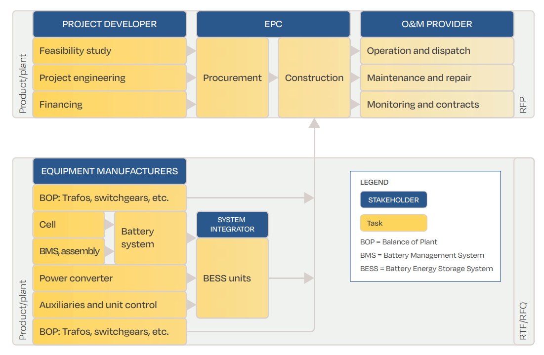
The risk profile of the project developer is a main determinant in defining value chain integration. A System integrator delivers typically a fully integrated BESS ,with all requisite components, up to a low or medium AC voltage level. Another key point to consider in procurement is the responsibility for communication between inverter and BESS as well as external parties (e.g., trader, grid operator). Furthermore, all components must be compliant with any local requirements. One main risk is that battery systems (especially the inverter) currently only have a prototype certificate instead of a unit certificate. The latter is required to be completely certified for European grids.
Product guarantees (here product guarantees with typical 2 years + 12 months) and performance guarantees (mainly on the battery capacity at a given duty cycle for 10 or 15 years) are a further important aspect of the selection process.
Finally, the delivery periods of the components should be considered. The battery modules are commonly sourced from South Korea or China and currently have delivery periods of five to nine months (this is due to rise). Due to the market force of a handful of suppliers, smaller volume sourcing is becoming increasingly complex.
13.5. Construction
The currently typical design of stationary storage systems in the range from 1 MW to 100 MW are container solutions with either all equipment in an ISO standard container, or part of the PCS equipment outside (skid-solution). Important variables to be considered are container sizes and type of to the cells is guaranteed. Newer formats are compact module blocks in outdoor housings that can be electrically interconnected to different topologies.
Battery containers need foundations, such as plinths or stripe foundations. In areas where high levels of ground protection are necessary (e.g., in water safety zones) special foundations to collect extinguishing water can be required. In usual circumstances this is not necessary if the container allows save flooding and includes a drainage system. The weight of the container depends on the equipment included when delivered (e.g., modules already pre-installed) and can go up to ~30 tonnes for a ~12 metre (40 ft) ISO container. Thus, in the overall plant design, space for a crane pad should be considered and access roads must be appropriate.
Furthermore, the location of the battery should be accessible for the fire brigade.
For the installation of containers without pre-installed modules one can calculate 2-3 person-days for one ~12 metre (40 ft) container, which equates to 500 modules.
The duration for commissioning depends on local conditions and should cover the electrical tests, communication tests, grid code compliance tests (depending on the country) and tests of the actual service to be provided (depending on application and country).